Author: Volume Concrete

  • Understanding Alkali-Silica Reaction (ASR) in Concrete

    Understanding Alkali-Silica Reaction (ASR) in Concrete

    Understanding Alkali-Silica Reaction (ASR) in Concrete

    Alkali-Silica Reaction (ASR) is a chemical reaction in concrete that can lead to significant deterioration, including cracking, expansion, and spalling. It occurs when the alkalis (primarily sodium and potassium) in the cement react with certain types of reactive silica found in aggregates, in the presence of moisture. This reaction forms a gel that absorbs water, expands, and exerts pressure within the concrete, leading to structural damage over time. Let’s break this down in detail.


    How ASR Occurs

    1. Components Involved:
      • Alkalis: These are typically sodium (Na⁺) and potassium (K⁺) ions from the cement, often present in the form of sodium hydroxide (NaOH) or potassium hydroxide (KOH). Alkalis can also come from external sources like deicing salts or seawater.
      • Reactive Silica: Certain aggregates contain reactive forms of silica, such as opal, chert, chalcedony, or strained quartz. These are often found in natural sands, gravels, or crushed rocks.
      • Moisture: Water is essential for the reaction to proceed, as it facilitates the formation and expansion of the ASR gel.
    2. The Reaction:
      • The alkalis in the concrete pore solution react with the reactive silica in the aggregates to form an alkali-silica gel (often a sodium or potassium silicate gel).
      • This gel is hygroscopic, meaning it absorbs water from the surrounding environment.
      • As the gel absorbs water, it swells, creating internal pressure within the concrete matrix.
    3. Resulting Damage:
      • The swelling gel exerts pressure that exceeds the tensile strength of the concrete, leading to micro-cracking.
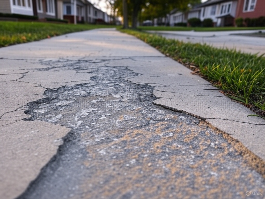
      • Over time, these cracks grow, causing visible damage such as map-like cracking patterns on the surface, expansion of the concrete, and in severe cases, spalling or pop-outs (where pieces of concrete break off).
      • The expansion can also cause misalignment in structures, such as bridges or pavements, and may lead to secondary issues like increased permeability, which allows more water and chemicals (e.g., chlorides) to penetrate, accelerating other forms of deterioration like rebar corrosion.

    Conditions for ASR to Occur

    For ASR to take place, three conditions must be present, often referred to as the “ASR triangle”:

    • Sufficient Alkalis: High alkali content in the cement (typically measured as Na₂O equivalent, where Na₂Oeq = Na₂O + 0.658 × K₂O). Cements with Na₂Oeq above 0.6% are considered high-alkali and more prone to ASR.
    • Reactive Aggregates: Aggregates containing reactive silica minerals. Some rocks, like certain volcanic rocks, siliceous limestones, or sandstones, are more susceptible.
    • Moisture: A relative humidity above 80% within the concrete is typically required for the gel to form and expand. Structures in wet environments or those exposed to frequent wetting and drying cycles are at higher risk.

    If any one of these conditions is absent, ASR will not occur.


    Signs and Symptoms of ASR

    • Cracking: A characteristic “map cracking” or “pattern cracking” on the surface, often with a network of fine, interconnected cracks.
    • Expansion: Measurable expansion of the concrete, which can cause joints to close, slabs to lift, or structural elements to misalign.
    • Gel Formation: White or grayish gel-like deposits may be visible at cracks or on the surface, sometimes exuding from the concrete.
    • Spalling and Pop-outs: In advanced stages, the surface may flake or chip, and small pieces of concrete may break off.
    • Staining: Discoloration around cracks, often due to the gel or secondary reactions.

    Impact on Concrete Structures

    ASR can significantly affect the durability and service life of concrete structures:

    • Structural Integrity: While ASR rarely causes immediate structural failure, the cracking and expansion can weaken the concrete over time, reducing its load-bearing capacity.
    • Aesthetic Damage: The cracking and spalling can make structures look unsightly, which is a concern for visible elements like sidewalks, walls, or architectural features.
    • Increased Maintenance Costs: Affected structures often require repairs, such as crack sealing, surface treatments, or even replacement of damaged sections.
    • Secondary Damage: Cracks from ASR allow water and aggressive chemicals (like chlorides) to penetrate, which can lead to rebar corrosion, further exacerbating deterioration.

    Testing and Diagnosis

    To confirm ASR in a concrete structure, several tests can be conducted:

    • Petrographic Examination: A thin section of the concrete is examined under a microscope to identify the presence of reactive aggregates, gel formation, and micro-cracking.
    • Expansion Testing: Core samples are tested in a lab to measure residual expansion potential under controlled conditions (e.g., ASTM C1293, the Concrete Prism Test).
    • Chemical Analysis: The alkali content of the cement and the presence of gel can be analyzed using techniques like scanning electron microscopy (SEM) or X-ray diffraction (XRD).
    • Field Observations: Visual inspection for characteristic cracking patterns, gel exudation, and expansion-related damage.

    Prevention of ASR

    Preventing ASR involves breaking the “ASR triangle” by controlling one or more of the necessary conditions. Here are some strategies:

    1. Use Non-Reactive Aggregates:
      • Test aggregates for reactivity using standards like ASTM C1260 (Accelerated Mortar Bar Test) or ASTM C1293.
      • If reactive aggregates must be used, blend them with non-reactive aggregates to dilute the reactive silica content.
    2. Limit Alkali Content:
      • Use low-alkali cement (Na₂Oeq below 0.6%).
      • Avoid external sources of alkalis, such as deicing salts containing sodium or potassium.
    3. Incorporate Supplementary Cementitious Materials (SCMs):
      • Add materials like fly ash, slag, or silica fume to the concrete mix. These SCMs can reduce the availability of alkalis by binding them into less reactive compounds and reducing the pH of the pore solution.
      • For example, using 25-40% fly ash can significantly mitigate ASR by reducing the alkali concentration in the pore solution.
    4. Control Moisture:
      • Design structures with proper drainage to minimize water infiltration.
      • Apply sealers or coatings to reduce moisture penetration into the concrete.
      • Ensure good curing practices to minimize early-age cracking, which can allow water ingress.
    5. Use Lithium Compounds:
      • Lithium-based admixtures (e.g., lithium nitrate) can be added to the concrete mix to suppress ASR. Lithium ions alter the reaction, forming a non-expansive gel instead of the swelling gel.
      • This method is effective but can be costly and is typically used in high-risk projects.
    6. Proper Mix Design:
      • Optimize the water-to-cement ratio to reduce permeability, making it harder for water to penetrate and facilitate the reaction.
      • Ensure proper curing to enhance the concrete’s durability and reduce the likelihood of cracking.

    Mitigation and Repair of ASR Damage

    If ASR has already occurred, mitigation and repair strategies can help manage the damage and extend the structure’s service life:

    1. Moisture Control:
      • Apply waterproofing sealers or coatings to reduce water ingress and slow the reaction.
      • Improve drainage around the structure to keep the concrete as dry as possible.
    2. Crack Sealing:
      • Fill cracks with epoxy or flexible sealants to prevent further water penetration.
      • This is a temporary measure and does not stop the underlying reaction.
    3. Surface Treatments:
      • Apply lithium-based treatments to penetrate the concrete and suppress further gel expansion.
      • Silane or siloxane sealers can also be used to reduce moisture ingress.
    4. Structural Reinforcement:
      • For critical structures, external reinforcement (e.g., carbon fiber wraps or steel plates) can be applied to manage expansion and maintain structural integrity.
      • In some cases, post-tensioning can be used to counteract the expansive forces.
    5. Replacement:
      • In severe cases, the affected concrete may need to be removed and replaced with ASR-resistant materials.
      • This is often the most expensive option and is typically a last resort.
    6. Monitoring:
      • Install strain gauges or crack monitors to track expansion and cracking over time.
      • Regular inspections can help determine the rate of deterioration and the effectiveness of mitigation measures.

    Real-World Examples and Research Insights

    • Case Studies:
      • ASR has been a significant issue in structures like the Seabrook Nuclear Power Plant in New Hampshire, where ASR-related cracking was identified in the 2010s. Mitigation involved monitoring, sealing cracks, and applying lithium treatments.
      • In Australia, the M4 Motorway in Sydney experienced ASR damage due to reactive aggregates in the concrete, leading to extensive repairs and the use of SCMs in subsequent projects.
    • Research:
      • Studies, such as those by the Portland Cement Association (PCA), have shown that using 20-30% fly ash can reduce ASR expansion by up to 70% in many cases.
      • The Federal Highway Administration (FHWA) has developed guidelines for ASR prevention, emphasizing the importance of aggregate testing and the use of low-alkali cements in high-risk areas.

    Conclusion

    Alkali-Silica Reaction is a complex deterioration mechanism that can significantly impact the durability of concrete structures, particularly in environments with high moisture and reactive aggregates. Understanding the conditions that lead to ASR and implementing preventive measures during the design and construction phases are key to avoiding its damaging effects. For existing structures, early diagnosis and appropriate mitigation strategies can help manage the reaction and extend service life. If you’re working on a specific project where ASR is a concern, testing aggregates and consulting with a materials engineer can provide tailored solutions to minimize risks.

  • Spalling Concrete in Depth

    Spalling Concrete in Depth

    Key Points to Prevent Spalling in Concrete

    • Research suggests using a low water-to-cement ratio (below 0.45) and air-entraining admixtures to reduce permeability and resist freeze-thaw cycles.
    • It seems likely that proper curing for at least 7 days, ideally 28 days, helps strengthen concrete and prevent surface deterioration.
    • The evidence leans toward applying a penetrating sealer 28 days after placement and reapplying periodically to protect against moisture.
    • An unexpected detail: creating control joints at 1/4 the slab depth can help manage cracking, reducing spalling risk in slabs.

    Preventing Spalling in Concrete

    Spalling in concrete, where the surface flakes or chips due to factors like freeze-thaw cycles, moisture, or chemical exposure, can be prevented with careful planning and maintenance. Here’s a clear guide for homeowners and builders:

    Mix Design and Materials

    Start with a concrete mix that has a low water-to-cement ratio, ideally below 0.45, to make it stronger and less permeable. Add air-entraining admixtures, especially in cold climates, to create tiny air pockets that help water expand during freezing without damaging the concrete. Use high-quality aggregates free from contaminants like clay, and avoid those prone to alkali-silica reaction (ASR), which can cause internal cracking.

    Curing and Finishing

    Cure the concrete properly by keeping it moist for at least 7 days, preferably 28 days, using methods like wet curing, curing compounds, or covering with plastic. This ensures it gains strength and resists surface weakening. During placement, avoid overworking the surface to prevent bringing excess water and fines to the top, and don’t pour on frozen ground—ensure proper compaction to eliminate voids.

    Sealing and Drainage

    After curing, apply a penetrating waterproofing sealer, like silane or siloxane-based options, 28 days after placement to block water and salt. Reapply every few years based on exposure. Design the structure with good drainage, such as sloping driveways or sidewalks at 1-2% grade, to prevent water buildup, which can lead to freeze-thaw damage.

    Reinforcement and Joints

    Use reinforcement like rebar or wire mesh to control cracking from temperature changes or loads. For slabs, create control joints at 1/4 the depth to manage cracking, reducing the risk of spalling. This is especially helpful for driveways or patios.

    Early Care

    Avoid using deicing salts, like sodium chloride, on new concrete during its first winter, as they can penetrate and corrode the surface, leading to spalling.

    Following these steps can significantly extend the life of your concrete, keeping it smooth and safe. For specific projects, consult a professional or check local building codes.


    Detailed Survey Note on Preventing Spalling in Concrete

    This note provides an in-depth exploration of preventing spalling in concrete, expanding on the key methods and incorporating technical details for a comprehensive understanding. Spalling, characterized by the flaking, chipping, or breaking off of concrete surfaces, is often caused by freeze-thaw cycles, moisture ingress, chemical exposure, or rebar corrosion. Preventive measures are crucial, especially in regions with harsh winters or high exposure to environmental stressors. Below, we detail the strategies, supported by recent insights and practical applications, ensuring a thorough guide for both professionals and laymen.

    Understanding Spalling and Its Causes

    Spalling refers to the deterioration of the concrete surface, manifesting as pitting, chipping, or peeling, which can compromise structural integrity and pose safety hazards like trip risks. Common causes include:

    • Freeze-thaw cycles, where water in concrete freezes, expands, and causes surface damage.
    • Moisture penetration, exacerbated by poor drainage or lack of sealing.
    • Rebar corrosion, where rusting steel expands and forces concrete apart, often due to carbonation or chloride ingress.
    • Chemical attacks, such as sulphate attack or alkali-silica reaction (ASR), which can weaken the matrix.

    Given these causes, prevention focuses on reducing permeability, enhancing durability, and protecting against environmental factors.

    Detailed Prevention Methods

    The following table summarizes the primary prevention methods, with specific details and considerations:

    MethodDescriptionKey ConsiderationsTiming/Interval
    Proper Mix DesignUse a low water-to-cement ratio (below 0.45) and air-entraining admixtures for freeze-thaw resistance.Ensure aggregates are free from contaminants like clay; avoid ASR-prone materials.During concrete mixing
    Quality MaterialsSelect durable, well-graded aggregates and sulphate-resistant cement for aggressive environments.Test aggregates for ASR potential; use supplementary cementitious materials like fly ash.Pre-construction
    Adequate CuringCure for at least 7 days, ideally 28 days, using wet curing, compounds, or plastic covering.Prevent rapid drying from wind or heat; ensure uniform hydration for strength.Post-placement, 7-28 days
    SealingApply penetrating sealers (e.g., silane, siloxane) 28 days after placement, reapply every few years.Choose sealers with anti-carbonation properties for exposed environments.28 days post-placement
    Proper DrainageDesign with slopes (e.g., 1-2% grade) to direct water away from surfaces like driveways.Ensure no water pooling; consider landscaping for additional runoff control.During design/construction
    Reinforcement and Control JointsUse rebar or wire mesh for cracking control; create control joints at 1/4 slab depth for slabs.Joints manage tensile stresses; reinforcement prevents structural cracks.During construction
    Avoid Deicing Salts EarlyRefrain from using salts like sodium chloride on new concrete during the first winter.Prevents chloride ingress and corrosion; use sand for traction instead.First winter post-placement
    Controlled Placement/FinishingAvoid overworking during finishing to prevent weak surface layers; compact to eliminate voids.Don’t pour on frozen ground; ensure proper vibration for compaction.During placement/finishing

    These methods address the most common causes, with additional considerations for specific scenarios. For instance, in areas with high CO2 exposure, ensuring adequate concrete cover over rebars (e.g., 40 mm vs. 30 mm, where 30 mm offers 25% less protection) and applying anti-carbonation coatings like MAPELASTIC GUARD can extend service life.

    Technical Insights and Additional Measures

    Beyond the basics, technical insights reveal further strategies:

    • Carbonation Protection: Carbonation reduces concrete’s alkalinity (pH ~12), exposing rebars to corrosion. Using low-porosity concrete and coatings with anti-carbonation properties, as noted in Mapei’s technical talk, can mitigate this. For repairs, undercutting corroded steel by approximately 20 mm and saw-cutting edges to 12 mm depth, followed by water-jetting at minimum 250 MPa, ensures a clean bond for patch materials.
    • Professional Installation: For large or visible surfaces, professional installation is recommended, especially in harsh winters, to minimize spalling risk. This includes using reliable tools like paddle mixers for consistent mixing, as highlighted in BN Products’ guide.
    • Environmental Factors: In regions with frequent wetting/drying cycles, adhering to good placement, compaction, and curing practices is critical to prevent defects like honeycombs or voids, which can accelerate moisture penetration.

    Practical Applications and Unexpected Details

    An unexpected detail for laymen might be the role of control joints, which are cuts made at 1/4 the slab depth to manage cracking, reducing spalling risk in slabs like driveways or patios. This is often overlooked but crucial for tensile stress management, as noted in BN Products’ guide. Another insight is the timing of sealing—28 days post-placement aligns with curing completion, ensuring the surface is ready for protection, a detail from Concrete Network’s advice.

    For homeowners, sealing every few years and avoiding deicing salts in the first winter are practical steps that can significantly extend concrete life, while builders might focus on mix design and reinforcement for long-term durability.

    Conclusion and Recommendations

    Preventing spalling in concrete requires a holistic approach, from mix design to ongoing maintenance. By following the outlined methods, such as using a low water-to-cement ratio, ensuring proper curing, and applying sealers, you can reduce the risk of surface deterioration. For specific projects, especially in aggressive environments, consult professionals or refer to standards like those from the American Concrete Institute (ACI), though direct ACI resources were not detailed here. This comprehensive strategy ensures both aesthetic and structural longevity, addressing the complexities of concrete behavior in various conditions.


    Key Citations

  • Foundation Calculator

    Foundation Calculator

    Concrete Foundation Volume Calculator

    Concrete Foundation Volume Calculator

    Footing Dimensions
    Wall Dimensions
    Total Concrete Volume: 0 cubic yards

    Concrete Foundation Volume Calculator

    Foundation Visual
    Total Concrete Volume: 0 cubic yards
  • Permeable vs. Non-Permeable Low Density Cellular Concrete LDCC

    Permeable and non-permeable Low-Density Cellular Concrete (LDCC) differ primarily in their ability to allow water to pass through, which is determined by the mix design and intended application. Here’s a breakdown of the two:

    Permeable LDCC

    • Definition: Permeable LDCC is engineered with a higher void content, allowing water to flow through it. The foam and aggregate structure creates interconnected air pockets or pathways.
    • Properties:
      • Permeability: High, typically designed to drain water at rates similar to coarse gravel (e.g., 100-300 inches per hour, depending on the mix).
      • Density: Still lightweight (20-90 pounds per cubic foot), but slightly denser than ultra-low-density non-permeable mixes due to adjustments in foam and cement content.
      • Strength: Lower compressive strength (e.g., 50-200 psi) compared to non-permeable LDCC, as the open structure sacrifices some load-bearing capacity for drainage.
    • Advantages:
      • Excellent for managing stormwater or groundwater around foundations, retaining walls, or pavements.
      • Reduces hydrostatic pressure by allowing water to dissipate quickly.
      • Can act as a drainage layer, eliminating the need for separate gravel or pipe systems in some cases.
    • Applications:
      • Backfill in areas with high water tables or heavy rainfall.
      • Subbase for permeable pavements or green infrastructure projects.
      • Situations where drainage is a priority over maximum strength.
    • Trade-offs: Reduced strength and insulation properties compared to non-permeable LDCC; may not be ideal where water infiltration needs to be minimized.

    Non-Permeable LDCC

    • Definition: Non-permeable LDCC is designed with a denser, closed-cell structure that prevents water from passing through. The foam cells are encapsulated, and the mix often includes less void space.
    • Properties:
      • Permeability: Very low (essentially waterproof once cured), with water absorption rates often below 10% by volume.
      • Density: Still lightweight (20-90 pounds per cubic foot), adjustable based on strength needs.
      • Strength: Higher compressive strength (e.g., 100-500 psi or more), as the closed-cell structure enhances load-bearing capacity.
    • Advantages:
      • Prevents water infiltration, reducing lateral pressure from water on foundation walls or structures.
      • Offers better insulation due to trapped air cells (thermal conductivity typically 0.1-0.3 W/m·K).
      • Provides a stable, uniform fill with no risk of water weakening the material over time.
    • Applications:
      • Backfill for foundations or retaining walls in wet environments where water resistance is critical.
      • Void filling under slabs or in confined spaces where settlement and water exposure must be avoided.
      • Projects requiring lightweight fill with moderate strength and insulation.
    • Trade-offs: Lacks drainage capability, so additional drainage systems (e.g., weep holes, gravel layers) may be needed in high-water areas.

    Key Differences

    FeaturePermeable LDCCNon-Permeable LDCC
    Water FlowAllows water throughBlocks water
    StrengthLower (50-200 psi)Higher (100-500+ psi)
    DensitySlightly higher voidsAdjustable, often denser
    DrainageExcellentNone
    InsulationModerateBetter
    Best UseDrainage-focusedStability-focused

    Choosing Between Them

    • Permeable LDCC is ideal when managing water flow is a priority, such as in flood-prone areas or where foundations need to “breathe” and drain efficiently.
    • Non-Permeable LDCC shines in scenarios where water resistance, higher strength, or insulation is more critical, like below-grade walls or in areas with poor natural drainage requiring separate water management.

    Volume Concrete LLC tailors the LDCC mix to project specs, so the choice depends on site conditions (e.g., soil type, groundwater), structural demands, and whether drainage or water resistance takes precedence.

    LDCC Pump Video

  • LDCC Low Density Cellular Concrete

    Low-Density Cellular Concrete (LDCC) from Volume Concrete LLC offers several advantages over traditional backfill materials like gravel or dirt for foundation backfilling, depending on the specific project needs. LDCC is a lightweight, flowable material made from a mixture of cement, water, and preformed foam, which creates air cells that reduce its density while maintaining sufficient strength. Here’s how it compares to gravel or dirt:

    1. Weight and Load Reduction: LDCC is significantly lighter than gravel or dirt, typically ranging from 20 to 90 pounds per cubic foot, compared to gravel (around 100-120 pounds per cubic foot) or compacted dirt (around 90-120 pounds per cubic foot). This reduced weight minimizes the vertical and lateral loads on foundation walls, which can be critical in areas with weak soils or where additional structural loading needs to be avoided.
    2. Flowability and Ease of Placement: Unlike gravel or dirt, which require mechanical compaction in layers, LDCC is highly flowable and self-compacting. It can be pumped into place, filling irregular voids and tight spaces around foundations without the need for heavy equipment or extensive labor. This makes it faster and more efficient to install, especially in confined or hard-to-access areas.
    3. Stability and Settlement: Gravel and dirt can settle over time if not properly compacted, potentially leading to uneven support under or around a foundation. LDCC hardens into a stable, uniform mass with minimal shrinkage, eliminating settlement concerns and providing consistent long-term support.
    4. Drainage and Permeability: Gravel is often chosen for its excellent drainage properties, allowing water to flow away from foundations. LDCC can be engineered to be either pervious or non-pervious, depending on the mix design. Non-pervious LDCC has very low permeability, reducing water infiltration and associated lateral pressure on foundation walls, which can be an advantage over gravel in wet conditions. However, if drainage is a priority, gravel might still be preferred unless a pervious LDCC mix is specified.
    5. Lateral Pressure: Gravel and compacted dirt exert lateral pressure on foundation walls, requiring robust structural design to resist these forces. Once cured, LDCC exerts no lateral pressure, offering a significant advantage for retaining walls or foundations where minimizing stress on adjacent structures is key.
    6. Cost and Time Efficiency: While gravel and dirt are generally less expensive upfront, LDCC can save costs in labor, equipment, and time due to its rapid placement and lack of compaction needs. Volume Concrete LLC’s LDCC, produced on-site with mobile batch plants, can further enhance efficiency by tailoring the mix to specific project requirements.

    That said, gravel or dirt might still be preferable in some scenarios. Gravel excels in drainage-critical applications, and dirt is a cost-effective option for simple projects with stable, well-draining soils. However, for foundations needing lightweight fill, reduced lateral pressure, or quick installation with minimal settlement risk, LDCC from Volume Concrete LLC stands out as a superior choice due to its unique properties and versatility. Project-specific factors like soil conditions, water table, and budget should ultimately guide the decision.

  • Riprap Grout on the Interstate

    Riprap Grout on the Interstate

    On a crisp March morning in 2025, the stretch of Interstate 5 just south of Portland, Oregon, buzzed with purpose. The Oregon Department of Transportation had a problem: drivers kept veering off the highway, carving rogue paths into the soft embankments. The solution? A line of locally sourced riprap boulders—gorgeous, rugged giants pulled from the Columbia River Gorge—paired with a grout fortress to lock them in place and keep vehicles where they belonged.

    The crew from Volume Concrete LLC rolled up at dawn, their mixer truck gleaming under the overcast sky. Beside them, AAA Concrete Pumping LLC’s rig hummed, its concrete line pump coiled like a python ready to strike. The boulders, each one a natural masterpiece, were already stacked along the embankment, a sturdy barricade waiting for its binding touch. The grout, a custom mix from Volume Concrete, was thick and gritty, crafted from local aggregates to match the land it would protect.

    “Alright, boys, let’s make it pretty!” hollered Mike, the crew chief, his grin wide as he waved the pump operator into action. The line pump whirred, snaking its hose over the riprap with precision. Gray grout flowed smooth and steady, cascading over the boulders, filling every crevice. No splatter, no waste—just clean, efficient work. The crew moved like a dance troupe, their faces lit with pride as the pump sped up the job, leaving the site spotless.

    “Keeps ‘em locked in for decades,” said Joey, wiping sweat from his brow, his smile mirroring Mike’s. “Ain’t no truck bustin’ through this.” The grout settled into place, hardening under the cool Portland air, its earthy tone blending with the boulders’ rugged beauty. By midday, the embankment stood transformed—a seamless blend of nature and craft, tough enough to shrug off anything the interstate threw at it.

    As the crew packed up, a passing driver slowed, peering out his window at the finished line. Mike caught his eye and tipped his cap. “Sleep easy, pal,” he muttered under his breath. “We got this.” The riprap and grout, born of Oregon’s own soil and sweat, stood ready—quiet sentinels along I-5, built to last.

  • Concrete Calculator Challenge

    Concrete Calculator Challenge

    Level: Beginner | Progress: 0/5

    Enter your answer (in cubic yards):

    Score: 0

  • Indus Valley Civilization

    Indus Valley Civilization

    Looks like you want some answers?

    Here are the answers to the questions about the Indus Valley Civilization:

    1. What are the two major cities of the Indus Valley Civilization?
      • The two major cities are Harappa and Mohenjo-daro.
    2. The Indus Valley people are known for their advanced urban planning. Can you name one key feature of their city layouts?
      • One key feature is their grid system of streets, which included well-planned residential and public areas.
    3. What was the primary writing system used by the Indus Valley Civilization, which remains undeciphered to this day?
      • The primary writing system is known as the Indus script.
    4. The Indus Valley Civilization had a remarkable sanitation system. What is one example of their advanced sanitation technology?
      • An example is their sophisticated drainage system, which included covered drains and public baths.
    5. Trade was an important aspect of the Indus Valley economy. Can you name one artifact that indicates they traded with Mesopotamia?
      • One artifact indicating trade with Mesopotamia is the Indus seals found in Mesopotamia, which were used for stamping goods.
  • URM UnReinforced Masonry Building

    URM UnReinforced Masonry Building

    Unreinforced masonry buildings (URM buildings) are structures made from bricks, stones, concrete blocks, or other masonry units that are not reinforced with steel bars (rebar) or other forms of internal support. These buildings rely solely on the weight of the masonry units and the mortar that binds them together for structural integrity.

    Key characteristics of URM buildings include:

    1. Lack of Internal Reinforcement: They do not have steel rebar or other internal supports to strengthen the masonry.
    2. Vulnerability to Earthquakes: URM buildings are particularly susceptible to damage or collapse during seismic events because they lack the flexibility and tensile strength provided by reinforcement.
    3. Historic Construction: Many older buildings, especially those built before modern building codes were established, are URM structures.
    4. Potential Hazards: In addition to earthquakes, URM buildings can also be vulnerable to other stresses such as strong winds, ground settlement, and heavy loads.

    Due to these vulnerabilities, many building codes now require retrofitting of URM buildings to improve their safety and performance in the event of earthquakes or other structural stresses.

  • Tofu Dreg Construction

    Tofu Dreg Construction

    Tofu-Dreg Construction: Understanding and Avoiding Shoddy Building Practices Worldwide
    Caution: Exploring Dangerous Building Failures Ahead!

    Tofu-Dreg Construction: Shoddy Building Practices Around the World

    This expanded article dives deep into “tofu-dreg” construction—a term for structures that look sturdy but crumble like tofu residue due to poor quality. Originating from Chinese slang, it highlights global issues in construction driven by cost-cutting, corruption, and negligence. We’ll explore more examples, causes, consequences, prevention strategies, and even test your knowledge with an interactive quiz.

    Origins and Meaning

    “Tofu-dreg” (豆腐渣) refers to substandard construction that prioritizes speed and savings over safety. It’s not limited to China; similar problems plague projects worldwide, from rapid urbanization in developing countries to overlooked maintenance in developed ones. These failures often result from systemic issues like weak regulations and profit-driven decisions.

    Global Examples of Tofu-Dreg Construction

    Below are expanded case studies with photos and details. Click to expand each for more info.

    Rana Plaza Collapse, Bangladesh (2013)

    An eight-story garment factory collapsed, killing 1,134 and injuring over 2,500. Built on unstable land with illegal extra floors and subpar materials, it exposed labor exploitation. Investigations revealed ignored cracks and overloaded structure.

    Rana Plaza aftermath
    Sampoong Department Store Collapse, South Korea (1995)

    A five-story store in Seoul collapsed, killing 502. Modifications like adding a restaurant floor without reinforcement, combined with inferior concrete, caused the failure. It led to major reforms in South Korean building codes.

    Sampoong collapse
    Hyatt Regency Walkway Collapse, USA (1981)

    Suspended walkways in a Kansas City hotel failed during an event, killing 114. A design flaw doubled the load on connections; poor oversight during changes was key. This spurred ethical discussions in engineering.

    Hyatt Regency collapse
    Grenfell Tower Fire, UK (2017)

    A London high-rise fire killed 72 due to flammable cladding added for aesthetics over safety. Cost-cutting ignored fire risks, leading to national cladding audits and regulations.

    Grenfell Tower fire
    Champlain Towers South Collapse, USA (2021)

    A Florida condo partially collapsed, killing 98. Corrosion, poor concrete, and ignored maintenance warnings were factors. It prompted inspections of similar buildings nationwide.

    Champlain Towers collapse
    Lotus Riverside Complex Collapse, China (2009)

    A 13-story Shanghai apartment toppled intact due to excavated soil piled nearby, destabilizing foundations. One worker died; it highlighted rushed urbanization risks.

    Lotus Riverside collapse
    Morandi Bridge Collapse, Italy (2018)

    A Genoa viaduct section collapsed, killing 43. Corrosion and design flaws in concrete stays, plus poor maintenance, were blamed. Italy audited infrastructure post-incident.

    Morandi Bridge collapse
    FIU Pedestrian Bridge Collapse, USA (2018)

    A new Miami bridge collapsed onto traffic, killing 6. Cracks ignored during stress testing and design errors caused it. NTSB cited multiple failures in oversight.

    FIU bridge collapse
    Mexico City Metro Overpass Collapse, Mexico (2021)

    Line 12 overpass failed, killing 26. Substandard welding, poor maintenance, and earthquake damage contributed. It sparked political debates on infrastructure funding.

    Mexico City Metro collapse
    Hard Rock Hotel Collapse, New Orleans, USA (2019)

    An under-construction hotel partially collapsed, killing 3. Weak flooring and ignored engineering warnings were factors. Demolition delays complicated recovery.

    Hard Rock Hotel collapse
    Hotel New World Collapse, Singapore (1986)

    A six-story hotel collapsed, killing 33. Structural design flaws and added weight from rooftop equipment caused it. Singapore tightened building inspections afterward.

    Hotel New World collapse
    Tacoma Narrows Bridge Collapse, USA (1940)

    The bridge oscillated and collapsed in wind due to aeroelastic flutter from poor design. No deaths, but it revolutionized bridge engineering with wind tunnel testing.

    Tacoma Narrows collapse

    Causes of Tofu-Dreg Construction

    • Cost-Cutting: Inferior materials, reduced reinforcements.
    • Poor Oversight: Corruption, skipped inspections.
    • Rushed Timelines: Inadequate curing, testing skipped.
    • Inadequate Design: Ignoring environmental factors like soil or weather.
    • Regulatory Gaps: Weak codes or enforcement in various regions.
    • Maintenance Neglect: Failing to address wear over time.

    Consequences and Statistics

    Building collapses cause thousands of deaths annually. According to global reports, over 2,000 die yearly from structural failures, with economic losses in billions. In developing nations, rapid growth amplifies risks.

    EventDeathsMain CauseReforms Triggered
    Rana Plaza1,134Overload, poor materialsGlobal labor standards
    Sampoong502Design changes, subpar concreteSouth Korean code overhaul
    Hyatt Regency114Engineering errorEthics in design
    Grenfell72Flammable materialsUK cladding bans
    Champlain98Corrosion, maintenanceUS condo inspections

    How to Avoid Tofu-Dreg Practices

    Detailed strategies for safe construction:

    • Hire certified contractors with references.
    • Use quality-tested materials; opt for volume concrete from reliable suppliers.
    • Adhere to codes; involve engineers for site assessments.
    • Conduct phased inspections and use tech like sensors for monitoring.
    • Plan for long-term maintenance, especially in harsh environments.
    • Educate stakeholders on risks; promote ethical practices.

    Test Your Knowledge: Interactive Quiz

    Question: What is a common cause of tofu-dreg failures?


    Updated: December 31, 2025 | Source: Volume Concrete Insights